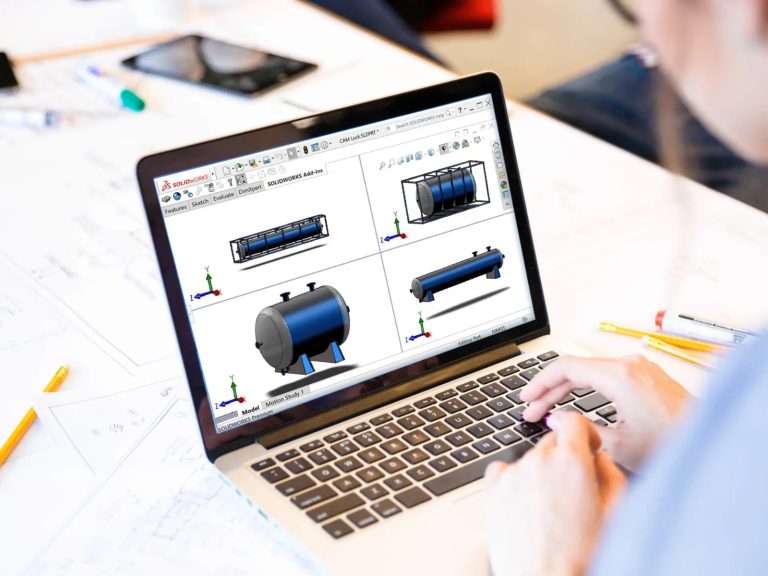
Solidworks

Why Solidworks training in Erode?

SOLIDWORKS Training in Erode is a 3D solid modeling computer-aided design (CAD) and computer-aided engineering (CAE).

SolidWorks is a 3D parametric design software that is used to design all sorts of products such as automobiles, marine equipment, airplane parts, cell phones, cameras, furniture, electrical assemblies, glasses, lighting fixtures, toys, vacuum cleaners, or any other like product you can think of.

What is the main purpose of SolidWorks?
SOLIDWORKS is usedto develop mechatronics systems from beginning to end. At the initial stage, the software is used for planning, visual ideation, modeling, feasibility assessment, prototyping, and project management

Why we should use Solidworks based Designs?

  • SOLIDWORKS Training in Erode the software tool lets you create, simulate, and publish while data management. This is a software program that provides the users a way to improvise the product design with real-time mechanism operation conditions and Real-time look-through Rendering while they work quick and on an economical basis.

Learning Outcome of Solidworks Course in Erode:

Introduction Solidworks Training in Erode

C Cube CAD Centre in Erode offers an in-depth SolidWorks course designed to empower engineers, designers, and students with the skills necessary to excel in 3D CAD modeling and design. SolidWorks, developed by Dassault Systèmes, is a leading software used extensively in product design, engineering, and manufacturing. Our course provides hands-on training and expert guidance to ensure you master the capabilities of SolidWorks and apply them effectively in your projects.

Syllabus

INTRODUCTION OF DESIGN CONCEPT AND PROCEDURE

  • Detailed Concept Of CAD
  • Need & Importance Of CAD
  • Overview About Actual Designing In Industries, Fundamentals Of Design And Its Implementation Methods
  • All Characteristics Of Solidworks To User Friendly Atmosphere
  • Superiority Of Solidworks With Its Use And Demand In Industries


TAKING THE SOLIDWORKS TOUR

  • Introduction To Solidworks.
  • System Requirements
  • Starting Solidworks In Windows
  • The Workbench Concept
  • Workbenches In Solidworks
  • Adjusting The Solidworks Interface
  • Creating And Managing Workspace
  • Graphic User Interface Of Solidworks
  • Menu And Toolbars
  • Opening Files
  • Creating New Files
  • Keyboard Shortcuts
  • Selecting/Moving Objects With Mouse
  • Working With Planes
  • Properties Toolbar
  • Changing The Properties
  • Changing The Interface From 3d Modeling To 2d

Sketching And Vice-Versa

  • Uses & Description About Feature Manager Design Tree
  • Working With Respect To Ucs.

Setting Up The Document Options

SKETCHER

  • Getting Started With Sketch
  • Creating Centerlines
  • Constructing Lines Constructing Ellipse
  • Constructing a Circle
  • Constructing an Arc
  • Creating Slots
  • Creating Polygon
  • Creating a Parabola
  • Creating a Spline
  • Equation Driven Curve
  • Point
  • Creating Text
  • Creating Construction Geometry
  • Rapid Sketch


EDITING SKETECHES

  • Sketch Fillet
  • Sketch Chamfer
  • Offsetting Entities
  • Converting Entities
  • Trim
  • Extending Entities
  • Jog
  • Mirror
  • Moving Sketch Entities
  • Moving Sketch Entities
  • Copying The Sketch Entities
  • Rotating Sketch Entities
  • Scaling Sketch Entities
  • Stretching Sketch Entities
  • Modify Sketch

Close Sketch Of Model

  • Sketch Picture
  • Area Hatch / Fill
  • Sketch Patterns
  • Blocks
  • Relations
  • Automatic Relations
  • Conflicts In Relations
  • Dimensioning
  • Dimension Property Manager
  • Exiting The Sketch
  • 3d Sketching


PART MODELING

  • Terminologies Used In Part Modeling Environment
  • Entering The Part Module
  • Choosing The Sketch Plane
  • Extruding Boss / Base Features
  • Revolving Boss / Base Features
  • Creating Sweep Features
  • Creating Loft Features
  • Creating Cut Features
  • Selecting Geometrics In Solid Works


REFERENCE GEOMETRY

  • Reference Planes
  • Creating New Planes
  • Creating Reference Axes
  • Creating Reference Points
  • Creating Reference Coordinate Systems
  • Editing Reference Geometries
  • Creating Curves


PLACED FEATURES

  • Creating Simple Holes
  • Creating Standard Holes Using The Hole Wizard

Creating Fillets

  • Creating Chamfers.
  • Creating Shell Features
  • Creating Rib Feathers
  • Creating Draft Feature
  • Creating Pattern


ASSEMBLY MODELING

  • Types Of Assembly Design Approaches
  • Working With Solid Works Assembly Bottom-Up Approach
  • Positioning The Components In Assembly
  • Assembly Mates
  • Standard Mates
  • Advanced Mates
  • Mechanical Mates
  • Smart Mates
  • Mate Reference
  • Replacing The Assembly Components
  • Rotating A Component
  • Moving Components
  • Detecting Interference
  • Assembly Pattern
  • Assembly Mirror
  • Creating Exploded View
  • Physical Simulation
  • Top Down Design
  • Assembly Performance
  • Configuration In Assembly
  • Smart Components
  • Smart Fasteners


DRAWING VIEWS & DETAILING

  • Introduction Of Drawing
  • Need & Importance Of Drawing
  • Starting The Drawing Workbench
  • Defining The Sheet & Sizes

Adjusting Of Drawing Sheet According To Object/Assembly

  • Types Of Projection
  • Using Predefined Drawing Styles
  • Scaling The Drafted View

DRAWING VIEWS

  • Creating Drawing From Part Or Assembly
  • Creating A New Drawing Document
  • Generating Standard Views
  • Derived Views
  • Creating Broken Views
  • Working With Assembly Specific View
  • Drawing View Properties
  • Manipulating Views


DETAILING

  • Creating Dimensions
  • Creating Model Dimension
  • Creating Auto Dimension
  • Dim-Xpert
  • Creating Smart Dimension
  • Creating Ordinate Dimension
  • Creating Chamfer Dimension


DATA EXCHANGE

  • Converting Files For Transferring
  • Converting Into IGES, STEP,PARASOLID Etc.
  • Convert Into Jpeg, Mpeg, Tiff, Pdf Files


SURFACE MODELING

  • Creating Surface Features
  • Creating Extrude Features
  • Creating Revolved Surface
  • Creating Swept Surface
  • Creating Lofted Feature
  • Boundary Surface
  • Creating Planar Surface

Creating Offset Surface

  • Creating A Radiate Surface
  • Extending A Surface
  • Creating Surface Fill
  • Creating Ruled Surfaces
  • Trimming Surface
  • Creating Mid- Surface
  • Replacing Faces
  • Deleting Faces
  • Un-Trimming Surface
  • Creating Knit Surface
  • Thickening A Surface
  • Move Faces


SHEET METAL MODELING

  • Fundamentals Concepts Of Sheet Metal
  • Using Sheet Metal Tools
  • Creating Base Flange
  • Creating Edge Flange
  • Creating Miter Flange
  • Creating Hem
  • Creating Log
  • Creating Break Corner/Corner-Trim
  • Creating Closed Corners
  • Creating Rip
  • Creating Sketched Bend
  • Creating Unfold/Fold
  • Flattening Sheet Metal Bends
  • Forming Tools
  • Cross Break
  • Welded Corner
  • Inserting Corner Trim
  • Creating Lofted Bends
  • Creating Sheet Metal Part By Converting A Solid Body


Weldment Design

  • Introduction to Weldment
    • 3D sketch
    • How to create user defined profile for structural member?
    • How to insert structural member?
    • How to apply gusset and fillet bead?
    • How to insert end cap?
    • Extruded Boss/Base
    • Trim/Extend
    • Mirror
    • placing holes
    • using different structural members, Weldment

Basic Geometric Dimensioning and Tolerancing

WhatsApp Image 2024-06-10 at 12.58.37 PM

SolidWorks Course

Duration
Lessons
Languages
Certificate
Software Covered
120 Hours
Online/offline
Tamil & English
Yes
1

This will close in 0 seconds

×