Creo

Why Creo training in Erode?

Creo Course in Erode is a First basic criteria of Computer Aided Design (CAD) usage software supporting Product Design for Discrete manufacturers and is developed by PTC. This Software consists of Modules, each delivering a distinct set of capabilities for a user role within product development.

Creo Training in Erode provides 3D CAD solution that helps you accelerate product innovation so you can build better products faster.Creo Training institute is Easy-to-learn seamlessly takes you from the earliest phases of product design to manufacturing and beyond.

Where does Creo Course Designs Applicable?

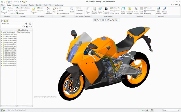
Creo Training in Erode is Parametric enables creation of solid, 3D models of a part and assembly models. The advantage of solid models is that they are realistic visual representation of designs; containing properties such as mass, volume and centre of gravity. Ptc Creo Course in Erode addition, 3D models can be used to check for interferences in an assembly, for strength analysis and also for manufacturing.

3D Solid Modelling : Allows creation of precise geometry, regardless of model complexity and automatically dimensions sketches for fast, easy reuse.

Robust assembly modelling: Creates simplified representations on the fly for smarter, faster assembly modelling performance.

Technical surfacing: Allows developing of complex surface geometry using sweeps, blends, extends, offsets and a variety of other specialized features

Freestyle surfacing: Allows quick creation of freeform shapes and surfaces using sub-divisional modelling capabilities. High quality, parameterized surfaces can be immediately reused in a 3D detailed design process.

Sheetmetal modelling: Allows creation of walls, bends, punches, notches, forms and reliefs using the streamlined user interface.

Weld modelling: Optimized user interface for the structural framework design process. Creo Parametric allows extraction of valuable information from the model, such as mass properties, clearances, interferences and cost data.

Why we should use Creo Training in Erode based Designs?

Creo training in Erode Parametric design capabilities provide the ability to create unique products and make them easily manufactural. Automatic updating of related design elements and the ability to design from concept to production using a single software application. PTC Creo software training software also includes visual simulation tools to enhance performance and meet quality standards, making it easy to construct parts using basic shapes, and the ability to utilize existing data to create new parts.

Learning Outcome of Creo course in Erode

Introduction to CREO Course Training at C Cube CAD Centre,

C Cube CAD Centre in Erode is proud to offer a comprehensive CREO course, designed to equip engineers, designers, and students with the skills required to excel in the field of 3D CAD modeling. CREO, developed by PTC, is a powerful and versatile 3D CAD software used extensively in product design and development across various industries. Our course provides hands-on training, expert instruction, and real-world project experience to ensure you master CREO’s capabilities and apply them effectively in your professional or academic pursuits.

Syllabus

INTRODUCTION TO CREO PARAMETRIC

  • Introduction to Creo Parametric

  • Feature-Based Nature

  • Bidirectional Associative Property

  • Parametric Nature

  • System Requirements

  • Getting Started with Creo Parametric

  • Important Terms and Definitions

  • File Menu Options

  • Managing Files

  • Menu Manager

  • Model Tree

  • Understanding the Functions of the Mouse Buttons

  • Ribbon

  • Toolbars

  • Navigator

  • Creo Parametric Browser

  • Appearance Gallery

  • Rendering in Creo Parametric

  • Colour Scheme Used in this Book

CREATING SKETCHES IN THE SKETCH MODE

The Sketch Mode

  • Working with the Sketch Mode

  • Invoking the Sketch Mode

The Sketcher Environment

Working with a Sketch in the Sketch Mode

Drawing a Sketch Using tools available in the Sketch Tab

  • Placing a Point

  • Drawing a Line

  • Drawing a Centreline

  • Drawing a Geometry Centreline

  • Drawing a Rectangle

  • Drawing a Circle

  • Drawing an Ellipse

  • Drawing an Arc

Dimensioning the Sketch

  • Converting a Weak Dimension into a Strong Dimension

  • Dimensioning a Sketch Using the Normal Tool

Dimensioning the Basic Sketched Entities

  • Linear Dimensioning of a Line

  • Angular Dimensioning of an Arc

  • Diameter Dimensioning Radial

  • Dimensioning Dimensioning

  • Revolved Sections

Working with Constraints

  • Types of Constraints

  • Disabling Constraints

  • Modifying the Dimensions of a Sketch

  • Using the Modify Button

  • Modifying a Dimension by Double-Clicking on it

  • Modifying Dimensions Dynamically

Resolve Sketch Dialog Box

Deleting the Sketched Entities

Trimming the Sketched Entities

Mirroring the Sketched Entities

Inserting Standard/User-Defined Sketches

Drawing Display Options

CREATING SKETCHES IN THE SKETCH MODE

Dimensioning the Sketch

  • Dimensioning a Sketch Using the Baseline Tool

  • Replacing the Dimensions of a Sketch Using the Replace Tool

Creating Fillets

  • Creating Circular Fillets

  • Creating Elliptical Fillets

Creating a Reference Coordinate System

Working with Splines

  • Creating a Spline

  • Dimensioning of Splines

  • Modifying a Spline

Writing Text in the Sketcher Environment

Rotating and Resizing Entities

Importing 2D Drawings in the Sketch Mode

CREATING BASE FEATURES

Creating Base Features

Invoking the Part Mode

The Default Datum Planes

Creating a Protrusion

  • Extruding a Sketch

  • Revolving a Sketch

Understanding the Orientation of Datum Planes

Parent-Child Relationship

  • Implicit Relationship

  • Explicit Relationship

Nesting of Sketches

DATUMS

Datums

  • Default Datum Planes Need for

Datums in Modeling Selection

Method in Creo Parametric Datum

Options

  • Datum Planes

  • Creating Datum Planes

  • Datum Planes Created On-The-Fly

  • Datum Axes

  • Datum Points

Creating Cuts

  • Removing Material by Using the Extrude Tool

  • Removing Material by Using the Revolve Tool

OPTIONS AIDING CONSTRUCTION OF PARTS

Options Aiding Construction of Parts

Creating Holes

  • The Hole Dashboard

  • Important Points to Remember While Creating a Hole

Creating Rounds

  • Creating Basic Rounds

  • Creating a Variable Radius Round

  • Points to Remember While Creating Rounds

Creating Chamfers

  • Corner Chamfer

  • Edge Chamfer

Understanding Ribs

  • Creating Trajectory Ribs

  • Creating Profile Ribs

Editing Features of a Model

  • Editing Definition or Redefining Features

  • Reordering Features

  • Rerouting Features

  • Suppressing Features

  • Deleting Features

  • Modifying Features

OPTIONS AIDING CONSTRUCTION OF PARTS

Introduction

Creating Feature Patterns

  • Uses of patterns

  • Creating Patterns

  • Deleting a Pattern

Copying Features

  • New Refs

  • Same Refs

  • Mirror

  • Move

  • Select

Mirroring a Geometry

Creating a Section of a Solid Model

  • Work Region Method

ADVANCED MODELING TOOLS

Other Protrusion Options

Sweep Features

  • Creating Sweep Protrusions

  • Aligning a Sketched Trajectory to an Existing Geometry

  • Creating a Thin Sweep Protrusion

  • Creating a Sweep Cut

Blend Features

  • Parallel Blend

  • Rotational Blend

  • General Blend

Using Blend Vertex

Shell Feature

  • Creating a Constant Thickness Shell

  • Creating a Variable Thickness Shell 8

Datum Curves

  • Creating a Datum Curve by Using the Curve Button

  • Creating a Datum Curve by Sketching

  • Creating a Curve by Using the Intersect Option

  • Creating a Curve by Using the Project Option

  • Creating a Curve by Using the Wrap Option

Creating Draft Features

ADVANCED MODELING TOOLS

Advanced Feature Creation Tools

Variable Section Sweep Using the Sweep Option

  • Swept Blend

  • Helical Sweep

  • Blend Section to Surfaces

  • Blend Between Surfaces

ADVANCED MODELING TOOLS

Advanced Feature Creation Tools

  • Toroidal Bend

  • Spinal Bend

  • Warp

  • Transform Tool

  • Warp Tool

  • Spine Tool

  • Stretch Tool

  • Bend Tool

  • Twist Tool

  • Sculpt Tool

ASSEMBLY MODELING

Assembly Modeling

Important Terms Related to the Assembly Mode

  • Top-down Approach

  • Bottom-up Approach

  • Placement Constraints

  • Package

Creating Top-down Assemblies

  • Creating Components in the Assembly Mode Creating Bottom-up Assemblies Inserting Components in an Assembly

Assembling Components

  • Displaying Components in a Separate Window

  • Displaying Components in the Same Window

  • 3D Dragger

  • Applying Constraints

  • Status Area

  • Placement Tab

  • Move Tab

  • Packaging Components

  • Creating Simplified Representations

  • Redefining the Components of an Assembly

  • Reordering Components

  • Suppressing/Resuming Components

  • Replacing

  • Assembling Repeated Copies of a Component

Modifying the Components of an Assembly

  • Modifying Dimensions of a Feature of a Component

  • Redefining a Feature of a Component

Creating the Exploded State

  • References Tab Offset Tab

  • Explode Line Tab

The Bill of Materials

Global Interference

Pairs Clearance

GENERATING, EDITING, AND MODIFYING THE DRAWING VIEWS

The Drawing Mode

Generating Drawing Views Generating the

  • General View Generating the

  • Projection View Generating the

  • Detailed View Generating the

  • Auxiliary View Generating the

  • Revolved Section View Generating the

  • Copy and Align View Generating the

  • 3D Cross-Section View

Editing the Drawing Views

  • Moving the Drawing View

  • Erasing the Drawing View

  • Deleting the Drawing View

  • Adding New Parts or Assemblies to the Current Drawing

Modifying the Drawing Views

  • Changing the View Type

  • Changing the View Scale

  • Reorienting the Views

  • Modifying the Cross-sections

  • Modifying Boundaries of Views

  • Adding or Removing the Cross-section Arrows

  • Modifying the Perspective Views

Modifying Other Parameters

  • Editing the Cross-section Hatching

  •  

DIMENSIONING THE DRAWING VIEWS

Dimensioning the Drawing Views

  • Show Model Annotations Dialog Box

Adding Notes to the Drawing

Adding Tolerances in the Drawing Views

  • Dimensional Tolerances

  • Geometric Tolerances

Editing the Geometric Tolerances

Adding Balloons to the Assembly Views

Adding Reference Datums to the Drawing Views

Modifying and Editing Dimensions

  • Modifying the Dimensions Using the Dimension Properties Dialog Box

  • Modifying the Drawing Items Using the Shortcut Menu

  • Cleaning Up the Dimensions

OTHER DRAWING OPTIONS

  • Sketching in the Drawing Mode

  • Modifying the Sketched Entities

  • User-Defined Drawing Formats

  • Retrieving the User-Defined Formats in the Drawings

  • Adding and Removing Sheets in the Drawing

  • Creating Tables in the Drawing Mode

  • Generating the BOM and Balloons in Drawings

SURFACE MODELING

Surface Modeling

Creating Surfaces in Creo Parametric

  • Creating an Extruded Surface

  • Creating a Revolved Surface

  • Creating a Sweep Surface

  • Creating a Blended Surface

  • Creating a Swept Blend Surface

  • Creating a Helical Sweep Surface

  • Creating a Surface by Blending the Boundaries

  • Creating a Variable Section Sweep Surface Using the Sweep Tool

Creating Surfaces the Using the Style Environment of Creo Parametric

  • Style Dashboard

Surface Editing Tools Mirroring

  • the Surfaces Merging the

  • Surfaces Trimming the

  • Surfaces Creating the Fill

  • Surfaces Creating the Intersect

  • Curves Creating the Offset

  • Surfaces Adding Thickness to

  • a Surface

  • Converting a Surface into a Solid

  • Creating a Round at the Vertex of a Surface

Freestyle modelling environment

  • Freestyle Dashboard

WORKING WITH SHEET METAL COMPONENTS

Introduction to Sheet metal

Invoking the Sheet metal Mode

Introduction to Sheet metal Walls

  • Creating the Planar Wall

  • Creating the Unattached Revolve Wall

  • Creating the Unattached Blend Wall

  • Creating the Unattached Offset Wall

  • Creating Reliefs in Sheet metal Components

  • Creating a Flat Wall

  • Creating a Twist Wall

  • Creating an Extend Wall

  • Creating a Flange Wall

Creating the Bend Feature

Creating the Unbend Feature

  • Creating the Bend Back

Conversion to Sheet metal Part

Creating Cuts in the Sheet metal Components

ANIMATION RENDERING WITH PROJECT

WhatsApp Image 2024-06-10 at 12.29.07 PM

Creo Course

Duration
Mode
Languages
Certificate
Software Covered
120 Hours
Online/offline
Tamil & English
Yes
1

This will close in 0 seconds

×